Plastic Crayons ,Plastic Crayons Doms,Plastic Crayon Colors,Erasable Plastic Crayons Wenzhou Jinbaicai Pigment Co.,Ltd , https://www.jbcbsdpigment.com
The Mark V control system is the third-generation digital electro-hydraulic turbine control system produced by GE, and is used in conjunction with the turbine generators it produces. It can be used for both gas turbines and steam turbines. Mark V can be configured as Simplex or Triple Redundancy (TMR). The Mark V of the 660 MW unit in our factory is configured as TMR.
The Phase III expansion project of Huaneng Dezhou Power Plant (#5 and 6 units) is two 660MW imported coal-fired units, and the turbine generator set and its control system are provided by General Electric of the United States. The project was formally started on September 28, 1999. The #5 unit entered the start-up phase of the entire group on April 29, 2002, completed the 168-hour trial run on June 29, and handed over production.
The Mark V control system is unique in considering the safety and reliability of the unit, and its three-redundancy design concept is unique. Because Mark V control system has a small number of turbines that are actually used for steam turbine control in China, there are not many people who know about this control system. Here, we use the Mark V control system applied to our plant's 660 MW unit as an example. Everybody gives a brief introduction. I hope to be inspired by professionals who are engaged in the design, manufacture, operation, and maintenance of turbine control systems.
2 system composition, principle and characteristics
The Mark V Turbine Control System is divided into two systems, Mark V and Small Mark V in our factory. The Big Engine refers to the turbine of the 660MW unit, and the Small Engine refers to the two turbines driving the boiler feed pump. Because the large-scale Mark V control system has a complex composition and complete functions, this article uses the Mark V control system as an example.
Simply put, Mark V control system consists of hardware and software.
The Mark V system hardware of the #5 unit consists of two control cabinets, two human machine interface (HMI) stations, printers, and hydraulic devices. The structure diagrams of the large and small machines and the EX2000 control system are shown in Figure 1. The software is easy to understand and modify. The BBL language is programmed. Several ATS algorithms are programmed in C language and can only be edited in the factory.
The basic components of the Mark V TMR turbine control system are briefly described as follows:
1. One of the two control cabinets is the main control cabinet and the other is the power cabinet (or auxiliary cabinet). The cabinet includes power supply and power distributors, general-purpose controllers, three redundant main controllers,,, protection controllers, power/load imbalance controllers, I/O signal controllers, and a large number of I/O signals. Terminal board. Mark V internal communication connection see Figure 2.
2. Two human interface stations (used with the small Mark V), one operator station and the other engineer station. The communication between the two human interface stations and the DCS (TXP system of Siemens AG, Germany) allows the Mark V system to be operated at the DCS operator station.
3. Provide 1600 psi oil pressure hydraulic device for the valve actuator and emergency trip system, installed in the steam engine room 0 meters below the hydraulic mechanical system to ensure the normal circulation of fluid.
4. After receiving the command signal from the turbine control cabinet, the hydraulic valve drive device uses high-pressure anti-fuel oil to drive the valve, and uses the valve position sensor to provide the valve position feedback signal for the control system. Hydraulic valve actuators and regulators are supplied by GE.
5. The turbine speed sensor, emergency trip valve and mechanical overspeed trip device are arranged in the front bearing housing of the turbine. 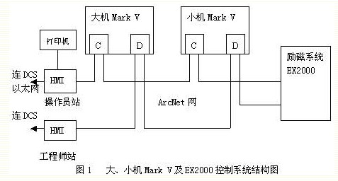
Mark V controls the basic principle of the system: the microprocessor collects all the input signals periodically, and then processes and calculates the signals according to the control program logic, and then outputs the calculated results to the valve control equipment of the steam turbine, thereby completing each of the turbines. Item control, protection and other important functions and other auxiliary functions. A large number of control logics, calculations, and protection logics are implemented in the microprocessors of the main controllers, and the most critical logic and protection functions (such as electronic over-speed protection, power/load imbalance control <PLU>, early valve actions < EVA> etc.) is done directly by the hardware logic. Whether the logic is done by software or by hardware, the relay or amplifier output is ultimately used to complete their respective functions.
Mark V control system features:
1. The power system is safe and reliable. The Mark V control system design has three independent and non-interfering switching
The power supply, two for the exchange of 220V (factory UPS and security section), all the way DC 110V (battery) power supply.
2. The control system has high reliability. Due to digital technology, software technology, software fault-tolerance (SIFT) technology and three redundant configurations, the Mark V TMR control system is flexible, accurate, stable, and reliable.
3. Fast operation speed. Each controller acts as a decentralized, multi-microprocessor controller with maximum data processing capability, high-resolution time stamps, and high-speed data acquisition capabilities (such as a digital signal sampling cycle of 1ms). The communication with the DCS is Ethernet-connected and redundantly configured with high speed and reliability.
4. Good technical performance. All-digital regulator control loop with excellent linear response characteristics.
5. Perfect control function. In addition to the conventional speed, load and flow control functions, it also has a strong self-diagnostic function, which can quickly isolate the faulty control module to ensure the normal and reliable operation of the system. When a fault occurs, the entire control system and each controller can be maintained online to maximize the safe and reliable operation of the unit.
6. More friendly man-machine interface. The PC-based human-machine interface station is equipped with a color display and a printer, and has parameters such as over-limit alarm, event recording, and trip memory. The display screen can be flexibly modified, and it can communicate with DCS flexibly and conveniently, and has online maintenance.
7. Modules that are directly interfaced with other units of the unit, such as TSI, CT, PT, etc. The entire control system has a compact layout, a reasonable structure, reliable work, and easy maintenance. 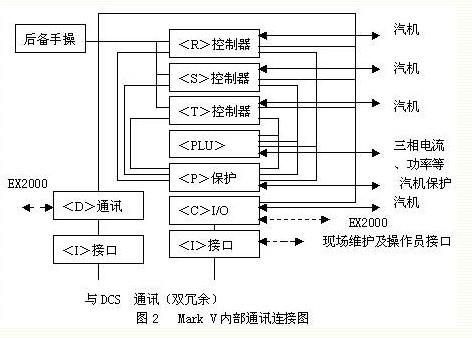
Based on the mathematical model and theoretical calculations, the following conclusions can be drawn:
Single-mode system: Mean time between failure MTBF=10000 hours
No repair TMR: Mean time between failures MTBF=8333 hours
Can Repair TMR: Mean Time Between Failure MTBF = 1675000 Hours
It can be seen that a small repair rate can greatly increase the MTBF of the system. Therefore, whether or not the online repair capability is essential to improve the reliability of the TMR system and extend the MTBF, and the TMR system without online repair capability is meaningless. TMR systems have online repair capabilities. In order to tolerate the failure of the voter in the TMR system, TMR technology can also be applied to the voter, and the voter in the Mark V (TMR) system is designed using TMR. Therefore, the MTBF thereof is extended to a greater extent. 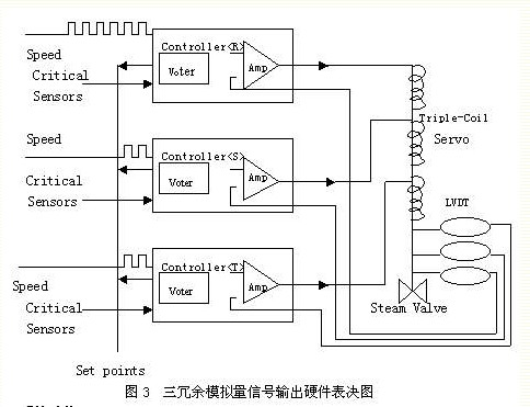
The Mark V TMR Turbine Control System has the following basic turbine control functions:
1.Automatically control the turbine speed and acceleration over the entire speed range and provide several discrete speed values ​​and acceleration ratings.
2. Automatically control the load and the load change rate from zero load to full load, and provide continuous load adjustment and load change rate.
3. When it is necessary to stop the automatic control part, but continue to supply power to the grid, use semi-automatic control of the speed and load.
4. Load limit, keep the operating parameters within the predetermined range, such as the load and main steam parameters to maintain the ideal value, or maintain the load within the user-defined range, such as changing the configuration of the power plant to increase the power plant load output capability.
5. Detect dangerous and unhealthy operating environments, alert the detected dangerous conditions and trigger the system to respond accordingly.
6. The monitoring control system includes its power supply and the status of redundant control loops.
7. Test the valve and control function.
Brief description of main functions:
1. Speed ​​control function
The speed control function is fully coordinated with the trip system. In the entire speed range, the turbine can be accurately adjusted from the crank speed to any speed in order to test the overspeed trip protection device.
The three speed sensors installed near the gears on the turbine shaft are respectively connected to three triple redundant speed regulating channels. The triple redundant speed control loop accurately adjusts the speed and acceleration of the unit after synchronization. The final control of the speed is determined by taking 3 out of 3 signals from the three electronic governor channels.
The speed control function also includes the synchronization function. The synchronization function is divided into three modes: manual synchronization, automatic synchronization and synchronous detection protection.
2. Load control function
The purpose of the load control function is to accept the reference value from the DCS, combine this value with the reference value in the load control function, and provide a flow reference value for the flow control function to achieve precise control of the unit load.
3. Flow control function - turbine valve control
Our 660MW steam turbine is equipped with two high-pressure main steam valves, four high-pressure control valves, two medium-pressure main steam valves, and two medium-pressure control valves, of which the #2 main steam valve has a bypass for warm-up valves. valve. High and medium pressure regulators adopt closed-loop control, and high and medium-pressure main steam valves adopt open-loop control, and their positions are fully open or fully closed.
4. Protection function
1) Power/Load Unbalance (PLU): The PLU function that is sensitive to the speed change rate is to quickly shut off the high-pressure control valve and the medium-pressure control valve under the load rejection conditions, so as to avoid overspeed due to high rotor acceleration.
2) Turbine protection: In critical operating conditions, the protective equipment protects the turbogenerator by tripping or deloading the turbine.
3) Emergency Overspeed Protection: There are two independent and redundant electrical overspeed protection systems.
5. Other control and monitoring functions
1) Automatic start of turbine (ATS) and sequence control: ATS accepts instructions from the operator through the operator interface or accepts commands from the DCS through the data transmission channel, and sends an execution command to the basic controller after comparing with the limit value. The ATS program can be executed in various operating modes.
2) Turbine operation with bypass operation (TBS): Turbine operation with bypass control system (Sulzer products, not within Mark V control range) is mainly used for unit startup and load rejection.
3) Turbine Monitoring Instrumentation: GE used Bently's sensors and preamplifiers to access the Mark V system to form a Turbine Generator Monitoring System (TGM). TGM monitors the parameters such as pressure, temperature, vibration, expansion, and eccentricity of the turbine, generator, and boiler feed-water pump turbine.
4 Application
Although the application time of Mark V control system in our factory is not long, its excellent control function has been well verified. The application of various control and protection functions in our factory is described below.
1. Speed ​​control function
Mark V control system can stably control the rotation speed of the turbine at the speed setting value, the static speed deviation control is 2 r/min, and the dynamic process is stable. In the early trial period, the static deviation of the speed control was relatively large (16 r/min). After debugging, the indicators have already met the requirements. In addition, Mark V also has acceleration control and wobble frequency function. When the speed is 2500 r/min warm up, the speed control wobbler is automatically put into operation. The wobble cycle is 1 minute, the wobble frequency is 84 r/min, and the wobble frequency is The purpose is to prevent the turbine wheels from operating at a constant speed that can cause resonance of the blades.
2. Load control function
The purpose of the load control function is to accept the reference values ​​of DCS, ATS, HMI, and other control devices, and combine these input values ​​with the reference values ​​in the load control function to calculate the flow reference value for the flow control function. Load control features include the following:
1) Load reference value; 2) Lift load rate; 3) Load return; 4) Valve position limit; 5) Load setting
Return value; 6) Main steam pressure limiter; 7) Adjustment valve test deviation; 8) Adjustment stage pressure feedback; 9) Valve reference value; 10) MW load limitation; 11) MW feedback; 12) Between CVR and VPL track.
Mark V control system power feedback function and DCS power feedback function at the same time may cause load instability, our factory Mark V control system basically operates in accepting DCS remote control mode, so its power feedback function is not put into operation.
3. Turbine self-starting function (ATS)
Mark V control system provides ATS function. The ATS software provides information in various modes. If the Mark V is in automatic mode, the ATS information will be used as the set value for the speed, load, and flow control functions. This method has not been applied in our factory; In semi-automatic mode, information from the ATS algorithm provides operator guidance, which is welcomed by operators. The control system provides the operator with the following important information: 1) high pressure rotor surface temperature, stress, predicted stress; 2) high pressure rotor center hole temperature, stress, predicted stress; 3) medium pressure rotor surface (center hole) temperature, stress, prediction Stress; 4) Medium pressure exhaust end surface (center hole) temperature, stress, predicted stress; 5) Main steam temperature recommended range; 6) Recommended range of reheat steam temperature, and many alarm retention information of turbine generator set for Operation personnel operation instructions.
4. Protection function
Mark V combines the control and protection functions of the steam turbine perfectly, especially the completeness of its protection function is worth learning from the domestic unit control system. In addition to the usual overspeed, large axial displacement, large vibration, large differential expansion, low oil pressure, low oil level in the fuel tank, low vacuum, high temperature exhaust gas, low hydraulic oil pressure, and tripping protection of the generator, etc. Added protection functions such as over-acceleration of acceleration, zero-speed inconsistent tripping of PLU, EVA, IVT (neutral valve closing), and TA (tripping expected). In this article, only its unique PLU, EVA, IVT, TA and other functions are briefly described.
1) The purpose of the PLU function is to quickly shut off CV1~CV4 and
IV1 & IV2, to prevent over-acceleration and overspeed tripping of steam turbines. Turbine power is corrected by reheat steam pressure, generator load is corrected by the sum of three-phase currents, and PLU occurs when the following conditions are met. (1) The difference between turbine power and generator load> 40% rated load; (2) Generator power loss rate> Rated load / 35ms. The PLU logic is completed by the controller hardware and can be tested separately during normal operation.
2) The IVT function is to quickly turn off IV1 & IV2 to maintain the turbine speed peak value when the load is more than 10% off.
Within the predetermined range. IV1&IV2 returns to the servo control after the quick close, and the unit returns to the stable operating condition of the speed control.
3) EVA function is when the power grid is unstable, IV quickly shuts down for about 1 second to reduce mechanical power and prevent hair
The continued increase in the motor power angle and the concomitant loss in the same period.
4) The TA function provides a trip reference value with a lower setpoint value that is proportional to the load reference value.
The range is between 106% (at 100% of rated load) and 104% (at 50% of rated load). At this time, the electrical tripping electromagnetic wire has an unblocked tripping function. When the peak speed of the turbine is higher than the TA reference value, the tripping is not locked. When the speed is lower than the reference value, the tripping device is reset, and the high and medium pressure main steam valve is reopened. Return to rated speed.
Although the above several superior protection functions have undergone meticulous static debugging, but for a variety of reasons, there is no dynamic test, and our plant uses the operation mode of the tripping turbine when the generator is disconnected, making these features of MarkV also difficult to give full play to .
5. Online test function
MarkV has the following online test features:
1) Valve activity test. When the operator starts the HMI and gradually closes the valve to 9% (in order to prove the reliability of the normal operation control equipment), the test quickly closes the solenoid valve action (proving the reliability of the snap protection device).
2) ETD1 (electrical trip device), ETD2, ETSV (emergency tripping solenoid valve) test, MarkV can test the tripping solenoid valve ETD1, ETD2, ETSV on-line to prove its reliable operation, but will not cause the turbine to trip. These functions are better applied in our factory.
In addition, like most domestic units, it also has on-line/off-line overspeed tests, valve tightness tests, and protection tests.
6. Problems that have occurred
During the trial operation, the EQ-2 solenoid valve of the balance valve was burned out, and the operation time was not long after the replacement and burned out again, and the QD2 terminal board burned out. The cause was that GE did not give a clear and credible reply.
5 Concluding remarks
Practice has proved that the Mark V control system produced by GE can meet the operational requirements of the 660 MW unit in our factory in terms of function and performance. (In late July, when the steam turbine efficiency experiment was conducted, the unit load was steadily controlled at 728 MW. A few hours left and right). Of course, it is not perfect, there are some inconveniences. For example, the display screen, system, and application software are all in English, and individual units are imperial; as the structure is too compact, there is a certain risk when online replacement of cards or power supply insurance is performed. At present, these problems are still difficult to solve.
1 Introduction The Mark V control system is characterized by Triple Redundancy (TMR) technology, which is not only the main controller three-redundancy, the modular redundancy in the protection controller, and the modules in the power/load imbalance controller. Three redundant, and its main measuring components (such as main steam pressure, reheat steam pressure, speed, shaft displacement, LVDT, etc.) and actuators (such as three-coil servo valve) are also three redundant, and the important analog output is Using hardware voting, the principle is shown in Figure 3. 3 system function
December 02, 2023